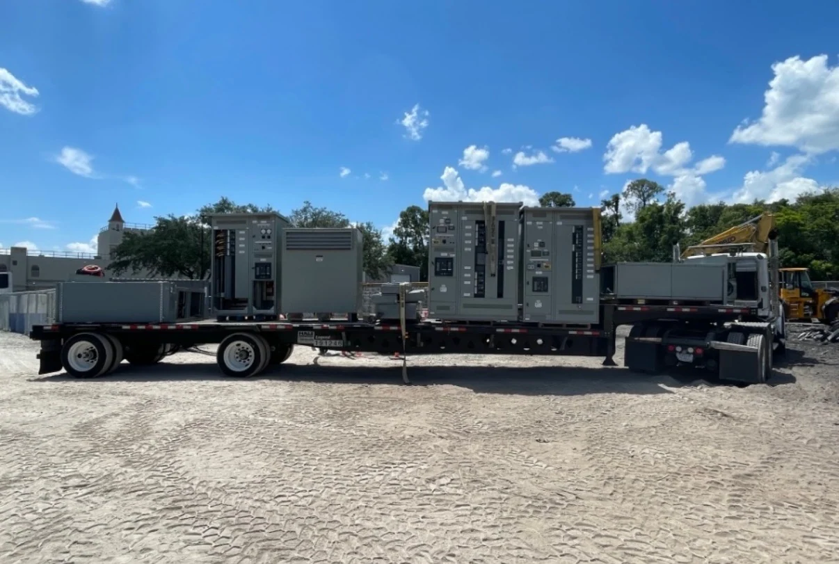
Start With the Industrial Feeder Duty
A Los Angeles industrial facility needs a medium-voltage switchgear specification built around its actual distribution system, not a generic product label. Begin with the one-line diagram, nominal system voltage, frequency, phase arrangement, grounding method, continuous load, transformer connections, and available fault current at each relevant bus. Identify whether feeders supply transformers, large motors, process equipment, or separate buildings. Those inputs let the design team define voltage class, interrupting or withstand requirements, bus arrangement, and protective-device interfaces before requesting project-specific equipment information from a manufacturer. Include planned load growth only when it is supported by the engineered distribution study, and distinguish normal operating current from emergency or standby conditions.
Define Voltage Class and Insulation Requirements
Voltage class should be selected from the electrical system, including maximum operating voltage and grounding conditions, rather than inferred from a nominal service description. Review insulation coordination, clearances, cable terminations, switching duties, and any applicable impulse insulation requirements with the responsible engineer. Outdoor exposure, coastal air, industrial contaminants, altitude, temperature, and indoor room conditions may affect enclosure and insulation decisions. For a California project, the equipment package should state the site conditions explicitly so the manufacturer can evaluate a new custom build with the right project assumptions. Record utility information separately from facility assumptions so changes can be traced during submittal review, and identify each feeder destination and operating priority.
Coordinate Transformers and Feeder Protection
Transformer connections influence both the lineup arrangement and the protection strategy. Provide transformer primary and secondary voltage, impedance, kVA, grounding details, inrush considerations, and the intended feeder operating sequence where available. For motor or process feeders, identify starting characteristics and whether protective relaying, fuses, circuit breakers, or other switching devices are contemplated by the engineered design. Time-current coordination should be reviewed across upstream and downstream devices, with settings determined by the study rather than assumed in a preliminary quote. Do not treat a familiar voltage name as a complete design instruction; confirm maximum system voltage, grounding arrangement, insulation level, and environment in approved documents.
Plan the Physical Lineup and Installation Interface
A technically suitable lineup must also fit the industrial facility. Share available room dimensions, equipment orientation, cable entry direction, termination space, access route, working clearances, housekeeping pad or foundation information, lifting constraints, and the location of adjacent transformers or distribution sections. Confirm whether the design is indoor or outdoor and identify enclosure, ventilation, drainage, environmental, and access requirements. These details help Switchgear Builders manufacture and supply new electrical switchgear custom to spec, while keeping installation responsibilities and field modifications clear. Protection discussions are strongest when they identify the design objective as well as the device, such as selective clearing, transformer protection, source isolation, or interlocking.
Prepare a Complete Manufacturer Quote Package
A useful quote request should include the one-line diagram, equipment schedule, site location, voltage and frequency, continuous-current needs, short-circuit data, transformer information, feeder count, control voltage, metering requirements, communications expectations, enclosure conditions, dimensions, cable details, and requested drawings or test documentation. State the desired operating sequence and identify who will approve submittals. Switchgear Builders manufactures, builds, and supplies new equipment in the United States using American components, with nationwide shipping; project-specific configuration, documentation, and commercial terms should be confirmed in the quotation. Show doors, removable sections, cable bending space, and the route from unloading point to final position on coordination drawings before fabrication details are finalized.
Review Standards, Testing, and Delivery Responsibilities
Before release, the engineer, owner, contractor, and manufacturer should agree on applicable standards, acceptance criteria, inspection points, test records, labels, drawings, and field coordination. If UL 891 is relevant to the specified assembly, confirm its applicability and any listing or capability for that particular project rather than assuming a blanket status. Establish shipping splits, packaging, receiving access, rigging, storage, and installation boundaries for the Los Angeles destination. Final protection settings, energization, and commissioning remain matters for qualified project personnel and the approved design. For a custom switchgear quote, separate mandatory requirements from preferences so configurations can be compared consistently against the same electrical and physical basis.