Start with the Louisiana Facility Load Profile
Planning Louisiana switchgear around automatic transfer switches begins with the loads that must remain energized, the sources available to serve them, and the operating consequences of a transfer. Identify normal and alternate source voltage, phase, frequency, grounding arrangement, continuous and starting currents, and whether loads are motor-driven, electronic, life-safety related, process-critical, or selectively shed. A qualified electrical engineer can then establish the source capacity, feeder ratings, available fault current, and sequence that the new manufacturer-built assembly must accommodate rather than treating the transfer switch as an isolated device. Also separate loads that may tolerate a delayed restart from loads requiring uninterrupted service, because that distinction influences sequencing, generator sizing, and control logic. Confirm whether future expansion, parallel sources, or a temporary maintenance source must be accommodated.
Coordinate Source Capacity and Transfer Sequence
An automatic transfer switch for critical facility loads is only one part of a coordinated distribution path. The design should state what initiates transfer, which source is preferred, how source availability is determined, whether retransfer is automatic or supervised, and how a generator or alternate source reaches stable operating conditions. Define time delays, in-phase or open-transition requirements where applicable, load-shed priorities, bypass or maintenance provisions, and manual controls with the engineer and controls team. Those decisions affect mains, bus sections, interlocks, control wiring, metering, and the physical lineup arrangement.
Account for Louisiana Site Conditions
Louisiana project conditions can vary substantially between an interior electrical room, a coastal or low-lying site, and an industrial or utility setting, so the equipment specification should describe the actual installation rather than rely on the state name alone. Document indoor or outdoor placement, ambient conditions, moisture and corrosion exposure, enclosure requirements, elevation, flood-protection measures, ventilation, cable-entry direction, working clearances, and access for maintenance. Site drawings should also show foundations, housekeeping pads, conduit approaches, lifting paths, and the route from receiving to the final equipment location. Where equipment is exposed to severe weather or salt-laden air, ask the design team to state material, coating, drainage, and inspection expectations explicitly. These conditions should be resolved in drawings and specifications before fabrication, not inferred from a shipping address.
Define the New Custom Switchgear Package
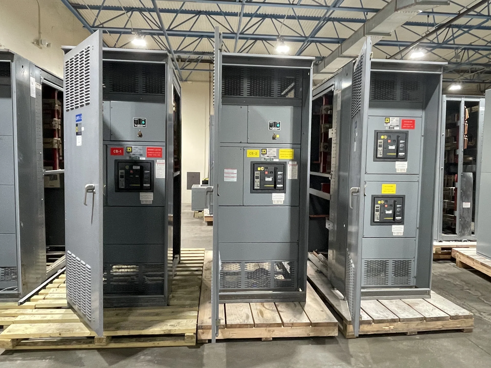
When requesting a Louisiana switchgear proposal, provide the one-line diagram, load schedule, source and generator data, equipment dimensions, protective-device information, control schematics, communication points, metering needs, and installation interfaces. State whether the scope is a complete new lineup or a coordinated section around separately specified transfer equipment, and identify the desired shipping split and field connections. Switchgear Builders manufactures new electrical switchgear in the United States, builds custom to specification with American components, and can coordinate nationwide shipping details for the project after scope and destination are defined.
Review Protection, Interlocks, and Maintenance Access
Protection and control review should test the proposed arrangement against both sources and every meaningful operating state. Check interrupting and withstand duties, selective coordination, grounding and bonding, generator contribution, transformer inrush where relevant, and settings that preserve critical loads without creating an unintended transfer sequence. Verify mechanical and electrical interlocks, source isolation, control-circuit power, alarm contacts, remote status points, and safe access to breakers, fuses, terminals, and transfer equipment. The final requirements should come from the responsible engineer and the approved project drawings. A written cause-and-effect matrix is useful when several sources, alarms, and permissives interact; it gives reviewers a common reference for normal, emergency, test, and abnormal conditions.
Plan Submittals, Delivery, and Field Coordination
Before fabrication, align submittal drawings with the electrical contractor, controls integrator, generator provider, utility or service authority when applicable, and the facility representative. Confirm dimensions, connection locations, nameplate data, shipping sections, lifting points, receiving responsibilities, and the inspection or test records required by the contract. For a Louisiana destination, confirm project-specific service responsibilities, component availability, freight terms, and delivery expectations. Any applicable standard, including UL 891 when the project calls for it, must be evaluated for that specific assembly and confirmed before commitments are made.