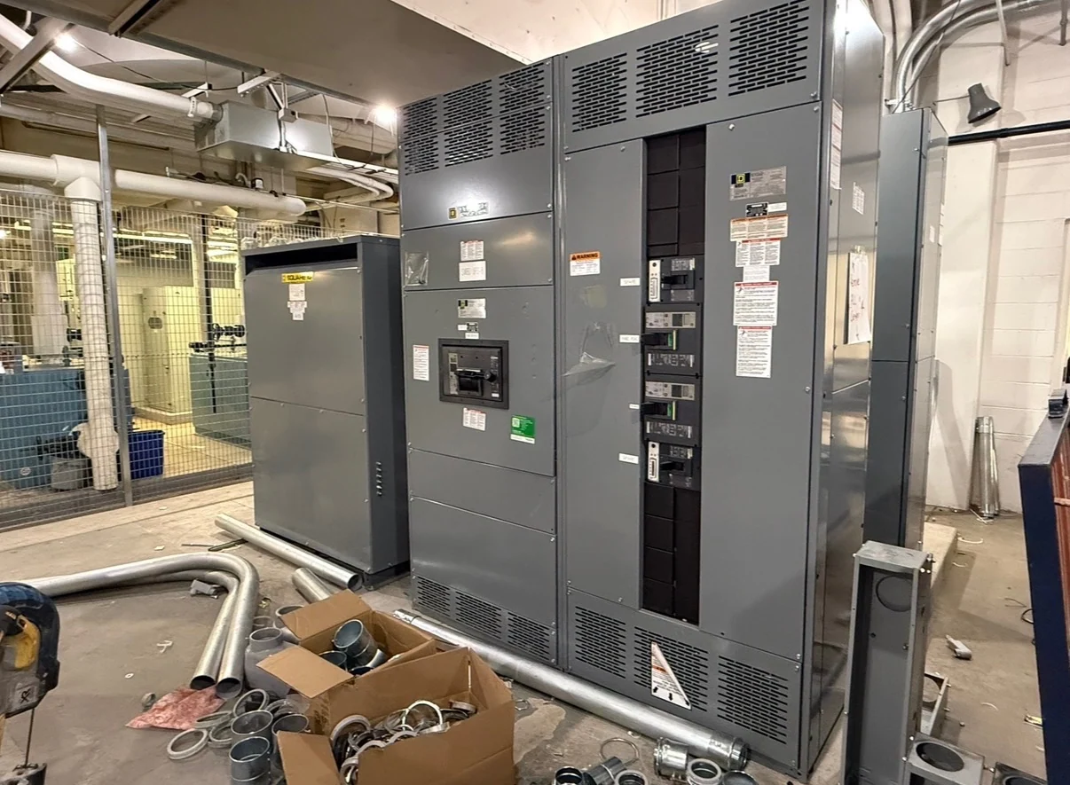
Plan the Boston Building Distribution Scope
A Boston commercial-building project begins with a clear description of how power enters, moves through, and leaves the facility. Identify the service arrangement, nominal voltage, phase and wire configuration, grounding method, calculated loads, available fault current, and anticipated expansion. Low-voltage switchgear for commercial building distribution may coordinate a main device, feeder breakers, metering provisions, bus sections, and a tie arrangement, but the correct combination depends on the engineer’s one-line diagram and study inputs. Switchgear Builders manufactures new electrical switchgear in the United States, builds custom equipment to specification, uses American components, and supplies projects with nationwide shipping. For a Boston project, coordinate the equipment scope and shipping plan with the project engineer and installing contractor.
Verify Ratings and Feeder Protection
Service ratings should be selected from the project’s load calculation and operating requirements rather than a building label or an assumed standard size. Review continuous current for the main, bus, and each feeder; interrupting ratings for protective devices; and the assembly short-circuit rating or withstand requirement applicable to the design. Feeder protection also requires attention to conductor ampacity, transformer characteristics, motor starting, selective coordination, and protective settings. Ask the electrical engineer to identify available fault current at the equipment location and any arc-flash study assumptions. A manufacturer quote is more useful when it includes these inputs, because changing one rating can affect device selection, bus arrangement, enclosure dimensions, and documentation.
Fit Equipment Into the Electrical Room
Physical planning matters as much as the single-line diagram. Provide the proposed equipment-room dimensions, door and corridor measurements, floor elevations, wall locations, cable-entry direction, working clearances, ventilation constraints, and the intended path from receiving to final placement. Confirm whether sections must be shipped separately and how the installer will handle lifting, staging, joining, and anchoring. In a dense commercial building, feeder bend space and access for operating or servicing devices can shape the lineup more than the available wall length. Coordinate switchgear dimensions with architectural, structural, mechanical, and fire-protection drawings, then have the responsible professionals confirm clearances and installation requirements for the particular Boston site. For Boston renovations and tenant fit-outs, document whether the lineup must pass through an existing loading area, freight elevator, corridor, or staged floor before final placement. Record turning radii, overhead obstructions, restricted delivery hours, and any temporary protection needed for occupied areas. A site walk with the electrical contractor can reconcile those constraints with section lengths, lifting points, cable pull space, and the planned shutdown sequence. If the project is near the waterfront or another exposed setting, ask the design team to identify environmental conditions that affect enclosure selection, corrosion considerations, and receiving protection. These details help distinguish a workable equipment layout from one that fits only on paper.
Coordinate Controls, Metering, and Interfaces
Commercial distribution equipment often connects several disciplines, so define interfaces before fabrication. Document utility metering requirements, main and feeder device functions, shunt or undervoltage trip needs if applicable, control power, remote indications, communication points, alarm contacts, and any main-tie-main operating sequence. Identify which signals belong to the building automation, emergency power, fire alarm, or energy-monitoring systems, and assign responsibility for field wiring and testing. Drawings should show terminal numbers, device tags, conduit entry expectations, and control-circuit segregation where required by the design. If UL 891 is specified, its applicability, construction requirements, and any project-specific listing or verification must be confirmed for this exact assembly rather than assumed from the equipment category.
Prepare a Complete Manufacturer Inquiry
For a productive inquiry, send the latest one-line diagram, load schedule, fault-current information, equipment schedule, floor plan, elevation constraints, specifications, control schematics, metering requirements, and requested drawing or test-document package. State the project location in Boston, Massachusetts, the receiving conditions, site access limitations, preferred shipping split, and the parties responsible for unloading and rigging. Request a scope that clearly separates included devices, enclosure features, controls, documentation, inspections, and shipping terms. Switchgear Builders can review a custom new-equipment request and develop equipment around the supplied requirements; final selection remains subject to engineering review, applicable authority or utility requirements, and confirmation of the project’s technical and commercial details.