Start with the water-treatment process
A motor control center for a Worcester water-treatment project should begin with the process narrative, not a preferred enclosure or starter brand. List raw-water, treatment, pumping, chemical-feed, dewatering, ventilation, and residuals-handling loads, then identify which motors operate continuously, intermittently, in duty and standby pairs, or only during abnormal conditions. A process engineer and electrical engineer can map each load to its source, feeder, control point, and operating consequence. That information helps a manufacturer organize a new custom MCC around actual sequences rather than a generic lineup. It also clarifies whether the project needs local controls, remote commands, automatic alternation, alarm contacts, or interfaces with a plant control system.
Define motor starting and drive choices
Motor starting method affects inrush current, acceleration behavior, mechanical stress, heat, and the control scheme. Across-the-line starters may suit some straightforward loads, while reduced-voltage starting or variable frequency drives may be considered where the process calls for controlled acceleration, adjustable flow, or reduced starting impact. A water-treatment specification should identify motor horsepower, voltage, phase, frequency, full-load current, starting requirements, overload approach, and any bypass or maintenance mode. For drives, add harmonic, heat dissipation, cable, grounding, communications, and programming expectations for engineering review. The final selection belongs to the project team after checking the motor, pump curve, utility conditions, and upstream distribution.
Account for Worcester site conditions
Worcester project documentation should describe the actual installation environment rather than relying on the city name as a design assumption. Identify indoor or outdoor placement, room temperature range, moisture, condensation, washdown exposure, corrosive chemicals, dust, elevation, ventilation, flood exposure, and the enclosure requirements established by the engineer. Note access routes, floor loading, working clearances, cable entry, conduit direction, and space for removing starters or drives. A custom manufacturer can use those inputs to coordinate enclosure layout, separation, heaters or ventilation if specified, and shipping sections. Environmental details also affect component selection and maintenance planning, so they should appear in the inquiry package and not only in field notes.
Coordinate controls and operating sequences
Controls should be described as operating behavior that can be reviewed, tested, and documented. For each pump or process motor, state the permissives, interlocks, HOA or local selector functions, remote start logic, lead-lag rotation, failure transfer, alarm conditions, emergency-stop behavior, and restart rules after a power interruption. Identify the intended interface to a supervisory control and data acquisition system or programmable controller, including discrete points, analog signals, network protocol, and ownership of the control logic. Clear point lists reduce ambiguity between the MCC builder, controls integrator, electrician, and plant operator. They also make factory functional checks more meaningful because the agreed sequence provides the acceptance reference.
Prepare an equipment information package
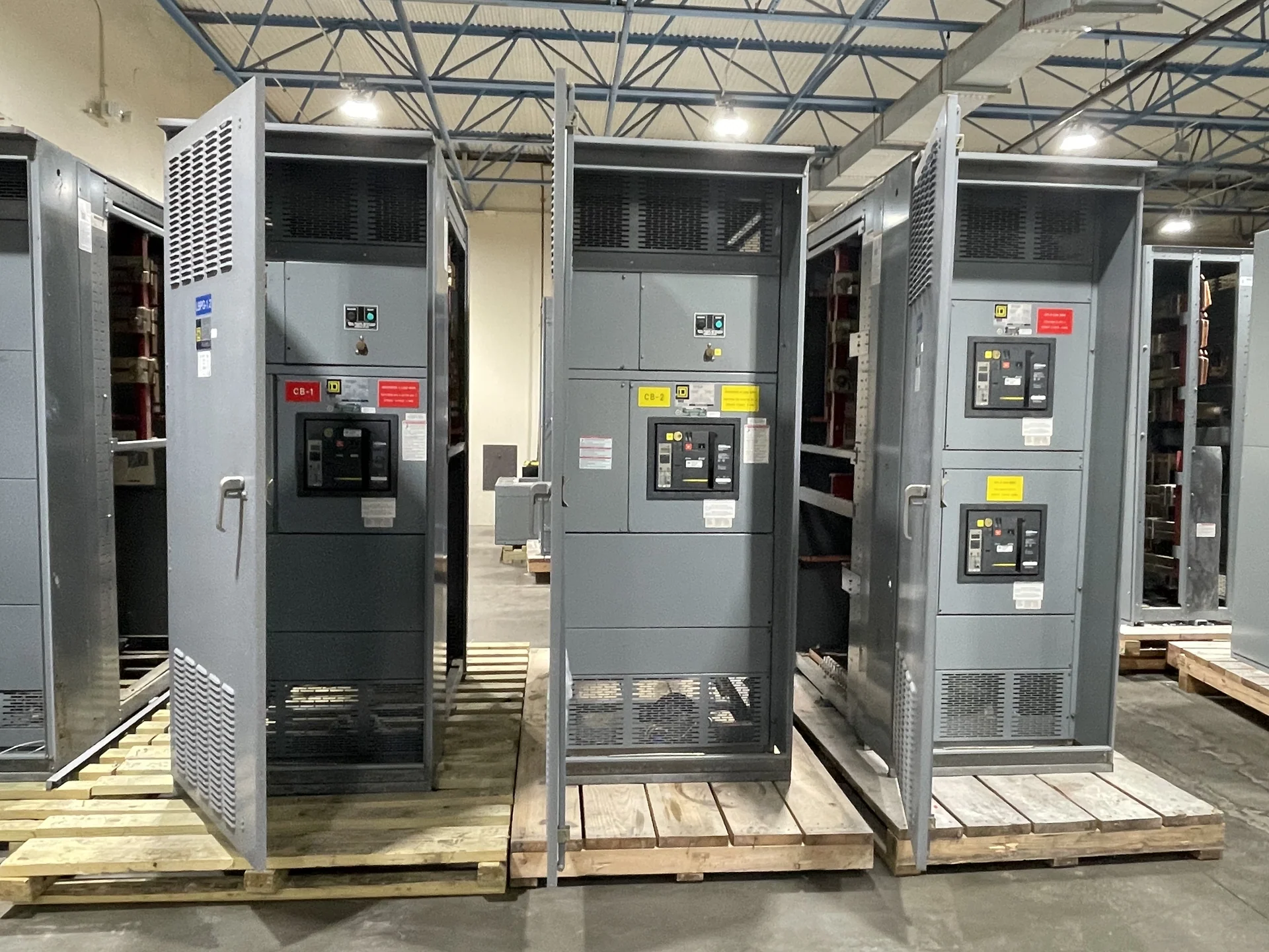
A useful request for new motor control centers for water treatment pumps and process equipment should include the one-line diagram, load schedule, motor list, control schematics, floor plan, cable schedule, utility data, fault-current information, and the applicable project specifications. Add the required bus arrangement, incoming connection, feeder count, starter or drive mix, spare provisions, metering, communications, nameplate data, paint or finish requirements, and documentation expectations. Ask the manufacturer to identify assumptions, exclusions, and items requiring engineering confirmation. Switchgear Builders manufactures new custom electrical equipment in the United States, uses American components, and can coordinate nationwide shipping; project scope still determines the final configuration.
Plan review, shipment, and installation coordination
Before ordering, the project team should align submittal drawings, dimensions, lifting points, shipping splits, receiving responsibilities, and the path from delivery to the electrical room. Confirm how the MCC will connect to upstream distribution, motor feeders, field instruments, grounding, and the plant control network. Review protective-device coordination, available fault current, arc-flash study inputs, and applicable local requirements with qualified professionals; do not treat a catalog description as a code determination. If UL 891 is considered for a particular assembly, its applicability and any required listing or verification must be confirmed for that project. Nationwide shipping can be planned around the destination and site constraints, but dates and freight terms require project-specific confirmation.