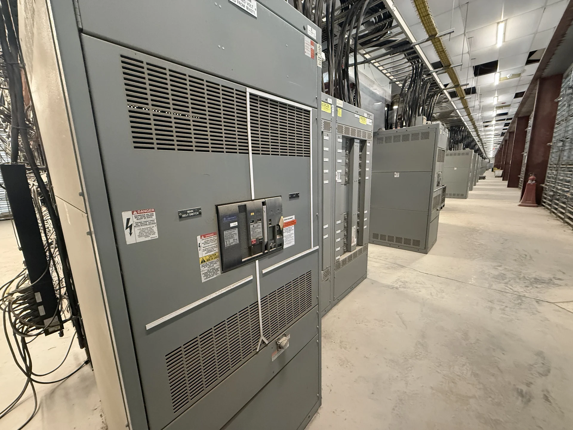
Start With the Industrial Feeder Scope
A Worcester industrial facility begins with an electrical distribution question, not a catalog label: which sources, transformers, process loads, and operating conditions must the new lineup connect? Medium-voltage switchgear for industrial facility feeders may include incoming sections, feeder switching, protective devices, metering, grounding provisions, and controls, but the correct arrangement depends on the one-line diagram and the site's operating sequence. Gather the utility or upstream source information, nominal voltage, frequency, phase arrangement, transformer data, feeder destinations, load calculations, and planned expansion before requesting a manufacturer quote. Also record whether the facility expects normally open or normally closed feeder arrangements, how switching authority will be controlled, and which signals must be exchanged with plant controls. If an expansion is phased, identify reserved sections and future cable routes without assuming that unused space automatically provides a suitable rating or usable capacity. Clear documentation of these choices reduces ambiguity between the engineer, manufacturer, installer, and commissioning team.
Confirm Voltage Class and Insulation Requirements
Nominal system voltage is only one part of a medium-voltage specification. The equipment voltage class, insulation level, basic impulse insulation level where applicable, continuous current, and short-circuit duties must suit the system and its grounding method. A manufacturer reviewing a Worcester project also needs to know whether conductors enter from above or below, how cable terminations are arranged, and what clearances the installation requires. These details affect compartment dimensions, bus arrangement, termination space, and the relationship between switchgear and transformers.
Coordinate Transformer Connections and Feeder Layout
Transformer connections should be shown explicitly rather than inferred from a feeder name. Identify primary and secondary voltages, transformer impedance information when available, grounding transformers or resistors, neutral treatment, phase rotation, and the intended isolation points. Feeder schedules should identify each destination, conductor arrangement, approximate load, starting characteristics for large motors, and whether a source or tie operating sequence is required. This information lets the design team evaluate physical routing and protection interfaces together instead of resolving incompatible connection assumptions during installation.
Develop Protection and Relaying Inputs
Protective relaying should be developed from a coordinated study and the actual available fault current, not from a generic setting copied between facilities. Provide the upstream protective-device data, transformer impedance, utility fault contribution if available, motor contribution assumptions, grounding method, and downstream device information to the electrical engineer. The resulting time-current review can inform relay functions, current-transformer requirements, trip logic, breaker or switch selection, and operating sequences. Settings, interlocks, and control power should remain subject to qualified engineering review and the project's approved documents.
Account for Fault Duty and Site Interfaces
Fault duty has both electrical and mechanical consequences. Specify the available fault current at each relevant bus, the required interrupting or withstand capability of the selected devices and assembly, and any changes expected from utility service revisions or additional generation. The equipment package should also address enclosure environment, indoor or outdoor placement, access, working space, anchorage, cable bending radius, grounding connections, and lifting or movement constraints. A Worcester installation plan should be checked against the actual room, foundation, conduit paths, and outage or tie-in sequence rather than relying on assumed dimensions.
Request a Complete New-Equipment Quote
Switchgear Builders manufactures new electrical switchgear in the United States, builds custom equipment to project requirements, uses American components, and supplies projects with nationwide shipping. For a useful quote, send the one-line diagram, equipment schedule, specifications, site conditions, required drawings, control narrative, testing expectations, delivery destination, and division of installation responsibilities. Ask the manufacturer to identify included devices, exclusions, assumptions, documentation, shipping configuration, and any questions requiring engineering decisions. Standards or listing requirements, including UL 891 when relevant to a particular assembly, must be reviewed and confirmed for that specific project rather than presumed.