Start with the Industrial Feeder Architecture
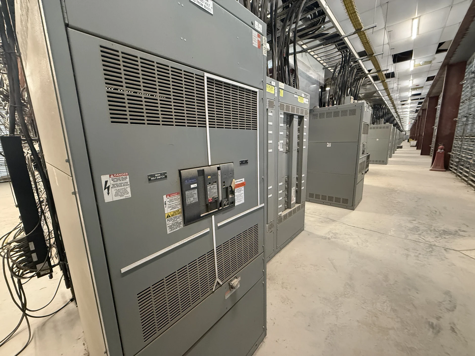
Medium-voltage switchgear for industrial facilities in Kansas City, Missouri should begin with the one-line diagram rather than a catalog label. Map the utility or generator source, incoming feeder, bus sections, transformer primary connections, downstream motors, and any alternate source. Identify whether the lineup serves one process area or distributes power across several buildings. A manufacturer can then develop new switchgear around the actual topology, operating sequence, cable entry, indoor or outdoor installation, and access constraints. The electrical design, site conditions, and authority requirements determine the equipment scope for the Kansas City project.
Define Voltage Class and System Grounding
Specify nominal system voltage, maximum system voltage, frequency, phase arrangement, and grounding method before comparing medium-voltage equipment. Nominal voltage alone does not establish the equipment voltage class or insulation requirements. The design package should also identify whether the feeder is solidly grounded, resistance grounded, or uses another engineered grounding arrangement, because those choices affect relay inputs, ground-fault detection, insulation coordination, and operating procedures. For a Kansas City industrial project, have the engineer confirm utility data and transformer characteristics, then ask the manufacturer to base a new lineup on documented electrical inputs rather than assumptions about a typical plant service.
Coordinate Transformer Connections
Transformer feeders deserve a dedicated review of primary termination, transformer impedance, inrush behavior, secondary protection, and the physical route between equipment and transformer. Provide transformer kVA, primary and secondary voltages, impedance information when available, grounding details, cable size and quantity, and the intended switching sequence. Those inputs help distinguish a feeder that primarily requires load switching from one that also needs carefully coordinated overcurrent and ground-fault protection. Confirm whether the transformer is indoor, outdoor, pad-mounted, or located in a constrained electrical area, because enclosure arrangement, cable compartments, working space, and shipping splits may change.
Set Protective Relaying Objectives
Protective relaying should be described in terms of the fault conditions and operating decisions the system must recognize. Identify phase overcurrent, ground-fault, undervoltage, overvoltage, frequency, breaker failure, or other functions only where the study and operating philosophy support them. Share available CT ratios, relay inputs, trip logic, communications needs, source interlocks, and the desired coordination boundaries with upstream and downstream devices. A time-current coordination study should establish settings; the switchgear quotation should reflect the agreed relay family, control voltage, wiring interfaces, event records, and testing documentation without treating any setting as universal.
Establish Fault Duty and Mechanical Requirements
Available fault current is a design input, not a generic regional value. Request the utility contribution, generator contribution where applicable, transformer impedance, motor contribution assumptions, and the study date used to calculate duty at each bus. Specify the required interrupting capability, short-time withstand, peak withstand, bus bracing, and grounding provisions as determined by the engineer and applicable project requirements. Also document altitude, ambient conditions, contamination or moisture exposure, seismic criteria when applicable, enclosure environment, cable bending space, and aisle clearances. These details let a manufacturer evaluate a buildable assembly instead of pricing an incomplete description.
Prepare a Manufacturer Quote Package
A useful request for new medium-voltage switchgear should include the one-line diagram, equipment schedule, site address, delivery access information, required lineup dimensions or limits, source and feeder count, breaker or switch functions, relay and metering requirements, control schematics, cable termination details, and documentation expectations. State whether factory inspection, witness testing, field assistance, or special packaging is part of the requested scope; each item must be defined and confirmed for the project. Switchgear Builders manufactures custom new electrical switchgear in the United States, uses American components, and can arrange nationwide shipping, while final configuration and commercial terms remain project-specific.
Review Standards, Testing, and Delivery Interfaces
Before release, the engineer, contractor, owner, utility, and manufacturer should agree on applicable standards, drawings, inspection points, test records, nameplate data, relay settings, and receiving responsibilities. If UL 891 is mentioned in the specification, confirm its applicability to the particular assembly and determine any project-specific listing or verification requirements; it should not be assumed for every medium-voltage arrangement. Coordinate shipping sections, lifting points, doors, removable components, storage conditions, and site rigging before fabrication. A written submittal review can resolve interfaces early and reduce uncertainty when the lineup reaches the Kansas City project site.