Start With the Critical-Load Definition
Planning automatic transfer switches for critical loads in Charlotte, North Carolina begins with a precise load schedule rather than a device choice. Identify which circuits require an alternate source, their voltage and phase, starting characteristics, steady-state demand, and acceptable interruption. Hospitals, data rooms, water systems, manufacturing controls, and emergency building functions can have different priorities. A qualified electrical engineer should separate truly essential loads from convenient loads, document operating assumptions, and confirm the governing project requirements before a manufacturer develops equipment information.
Confirm Both Sources and Their Capacity
An automatic transfer switch can only transfer a critical load when the normal and alternate sources are properly defined. Provide source voltage, frequency, phase arrangement, available fault current, grounding method, service or feeder origin, and the capacity available during the proposed transfer condition. The alternate source might be a generator or another distribution source, but its starting response, sustained capacity, and load-step limits must be coordinated with the transfer sequence. Source data should be checked against the one-line diagram and utility or generator design requirements.
Design the Transfer Sequence
Transfer logic should describe what the switch monitors, which source-failure conditions initiate action, and how retransfer occurs after normal power returns. Important questions include open or closed transition, time delays, in-phase or synchronized operation where applicable, generator start signaling, source availability sensing, bypass or isolation needs, and manual operating provisions. A written sequence of operations prevents ambiguous assumptions between the engineer, controls designer, installer, and manufacturer. Each delay and interlock should be reviewed for the actual critical loads, source behavior, and facility operating procedures.
Coordinate Protection and Distribution Interfaces
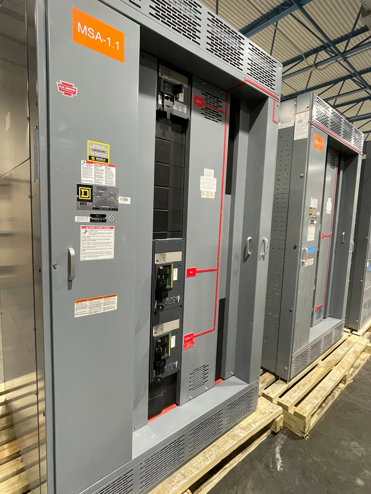
Protection coordination must account for the transfer switch, upstream overcurrent devices, downstream feeders, and both available sources. Request the calculated fault current, breaker or fuse information, trip settings when available, conductor details, and selective-coordination objectives for the equipment package. The transfer switch rating and construction must be selected for the project-defined duty, not inferred from load amperage alone. Where an automatic transfer switch connects to custom switchgear or switchboards, confirm terminals, bus connections, control wiring, neutral treatment, grounding and bonding, and enclosure interfaces on coordinated drawings.
Plan Maintenance Access in the Charlotte Facility
Physical planning matters as much as the electrical sequence. Share the room layout, equipment footprint, working clearances, door and cable-entry orientation, ventilation conditions, lifting path, and access restrictions for the Charlotte project. Maintenance personnel may need to inspect controls, operate a manual mechanism, isolate equipment, or verify source indications without obstructing adjacent distribution equipment. The design team should also establish how critical loads remain supplied during planned maintenance and what procedures apply during testing. Final dimensions, interfaces, and access provisions belong in the project drawing review.
Prepare a Manufacturer Quote Package
For a useful quote on new automatic transfer equipment or a coordinated switchgear assembly, send the one-line diagram, load schedule, source information, transfer sequence, protection requirements, enclosure location, dimensions, control and monitoring points, required drawings, testing expectations, destination, and installation responsibilities. Switchgear Builders manufactures new electrical switchgear in the United States, builds custom to project specifications, uses American components, and ships nationwide. The applicable equipment type, standards, and any UL 891 requirement or project-specific listing must be confirmed for the particular design rather than assumed from a general inquiry. Include the required number of sources and transfer sections, preferred device arrangement, remote status points, alarm contacts, communications protocol, bypass provisions, and any coordination-study assumptions. If the equipment replaces an existing lineup, add field-verified dimensions, connection locations, photographs, and the planned outage approach. Those inputs help the manufacturer distinguish confirmed requirements from open design questions, identify interfaces that need engineer approval, and prepare a clearer equipment scope for review by the project team.