Plan the Raleigh Service Entrance Around the Utility Interface
A Raleigh electrical distribution project starts with a clear definition of the service entrance: utility voltage, phase and wire arrangement, service capacity, metering method, disconnecting means, and the point where utility and customer responsibilities meet. Commercial and industrial sites may have different service rules, transformer arrangements, and access constraints, so the design team should confirm current requirements with the serving utility and the authority having jurisdiction. Switchgear Builders manufactures new electrical switchgear in the United States, builds custom equipment to specification, uses American components, and can coordinate nationwide shipping for the defined project scope. For a Raleigh-area design review, record the service point, transformer ownership, proposed service date only as a planning input, and the utility's required submittal sequence; these details prevent a metering compartment from being designed around assumptions.
Select a Service-Entrance Switchboard Configuration
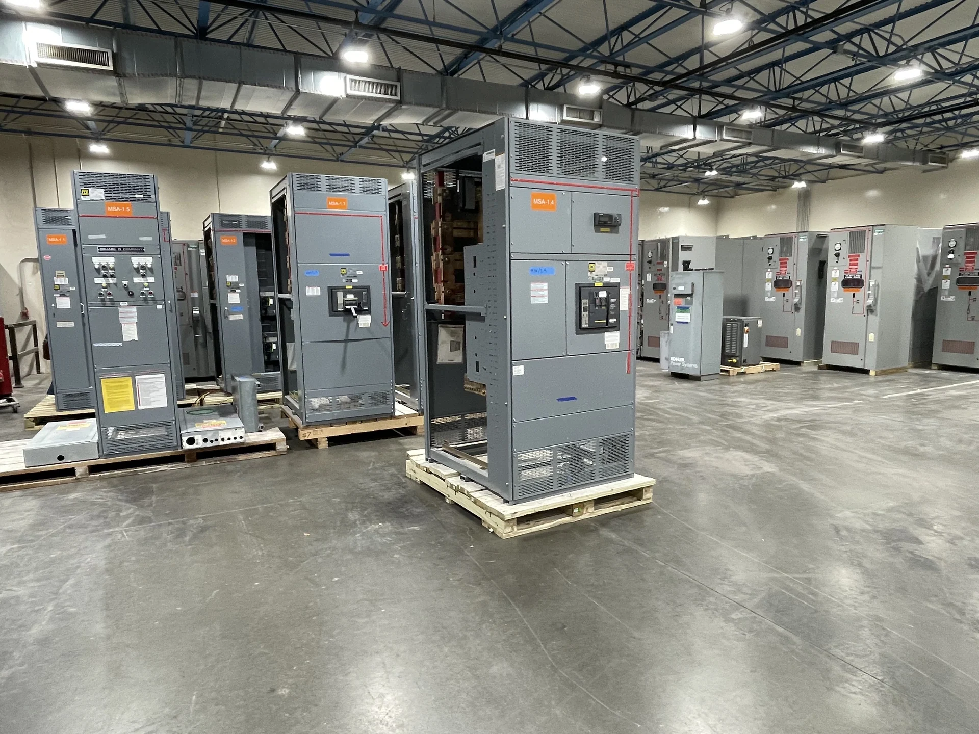
Service-entrance switchboards can be arranged around a main disconnect, multiple service disconnects, feeder sections, metering compartments, or a combination selected for the facility. The choice affects footprint, conductor routing, maintenance access, protection coordination, and how future feeders may be added. A commercial building might prioritize organized tenant feeders and utility metering space, while an industrial plant may need larger feeder conductors, motor-related loads, and a layout that supports process expansion. The one-line diagram, load schedule, equipment elevations, and installation clearances should be reviewed together before a manufacturer quote is finalized.
Account for Metering and Disconnecting Means
Metering details should be settled before fabrication because instrument transformers, meter sockets or compartments, test provisions, sealing arrangements, and conductor paths can change the internal layout. Ask the utility which metering method, access arrangement, labeling, and approval process applies to the Raleigh site; do not assume that a configuration accepted elsewhere will fit this service. Disconnecting means also require careful review of device locations, number of service sections, operating sequence, handle access, and coordination with the service conductors. Those inputs help the builder separate utility-facing requirements from owner-selected distribution features.
Verify Feeder Circuits and Available Fault Current
Feeder planning should identify every outgoing circuit, its calculated load, conductor size and routing, protective device type, continuous current requirement, and connection to downstream equipment. Available fault current at the service matters when selecting equipment and protective devices; the value should come from a qualified electrical study or the utility and be checked against the proposed assembly and device ratings. Changes to a transformer, service size, source arrangement, or feeder plan can alter the result. Providing the study basis, coordination objectives, and expected future loads gives the manufacturer a more reliable foundation for custom design. A preliminary fault-current value should be tied to the actual transformer impedance, conductor length, and source configuration; if any of those inputs change, recalculate before release. Document spare section space separately from spare breaker capacity, since they affect enclosure dimensions and future work differently.
Coordinate Physical Details for Commercial and Industrial Sites
A technically suitable lineup still needs to reach its installation location and fit the building interface. The project team should document indoor or outdoor placement, enclosure environment, room dimensions, working clearances, cable entry, floor or housekeeping-pad conditions, lifting path, shipping splits, and space for operation and maintenance. Industrial sites may add exposure, vibration, process shutdown, or specialized control requirements; commercial sites may impose tighter access and coordination with architectural finishes. Review these conditions with the electrical engineer, contractor, utility, and manufacturer so the new equipment is detailed for the actual Raleigh project rather than a generic application. Include elevation views showing cable lugs, neutral or ground provisions, and meter access, then mark owner-furnished devices and responsibilities. A quote package that distinguishes required equipment from field-installed accessories is easier for the engineer and contractor to compare.
Prepare a Direct Manufacturer Quote Request
For a useful quote, send the manufacturer the project location, one-line diagram, service voltage and frequency, phase and grounding arrangement, available fault current, continuous current and feeder schedule, metering requirements, enclosure environment, dimensions, control or interlock sequence, documentation expectations, and desired shipping destination. Identify whether the equipment is for new construction, an expansion, or a planned replacement, and explain outage, rigging, site-access, and schedule constraints. Switchgear Builders can evaluate a new custom build for the stated requirements, provide project-specific scope and commercial terms, and ship nationwide after the equipment and logistics are defined.