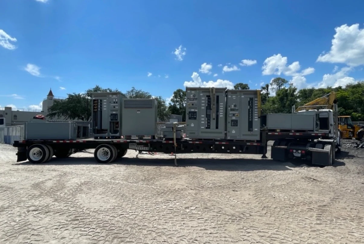
Start with the Tulsa project conditions
A Tulsa industrial power project should begin with the electrical conditions at the particular site, not with a generic equipment label. Identify the utility or generation source, nominal system voltage, frequency, phase arrangement, grounding method, available fault current, continuous load, motor contribution, and expected expansion. For a facility feeder, also document transformer size and impedance, feeder length, cable type, environmental exposure, elevation or outdoor interfaces, and the operating sequence expected during maintenance or abnormal conditions. Switchgear Builders manufactures new electrical switchgear in the United States, custom to specification, using American components and shipping nationwide. The engineer of record establishes the applicable design criteria and local requirements for the Tulsa-area project.
Choose the appropriate medium-voltage class
Medium-voltage switchgear selection depends on more than the nominal voltage printed on a one-line diagram. Confirm the system voltage and grounding arrangement, then select an equipment voltage class with adequate insulation coordination for the installation. The specification should distinguish continuous current from short-circuit duty and should identify the interrupting requirements of each switching or protective device. For industrial facility feeders, the lineup may need a main, feeder sections, transformer connections, bus sectionalizing, metering, or provisions for a defined future circuit. A custom build should reflect the actual feeder topology, cable terminations, compartment access, indoor or outdoor placement, and working-clearance constraints rather than forcing the project into an unsuitable standard arrangement.
Coordinate transformer and feeder interfaces
Transformer connections deserve a coordinated review because the transformer affects both normal operating current and fault behavior seen by the medium-voltage lineup. Provide transformer primary and secondary voltages, kVA or MVA, impedance, grounding details, inrush considerations, and the intended connection method. On the feeder side, identify conductor sizes, parallel runs, termination requirements, routing direction, shield grounding, and the physical transition into the equipment. These inputs help define bus arrangement, device selection, cable-entry space, and isolation points. The final design must also account for downstream loads such as large motors, drives, or process equipment, with qualified engineers checking compatibility and coordination across the complete distribution system.
Build a practical protective-relaying scheme
Protective relaying should be developed from the facility's protection philosophy and study inputs rather than selected as an afterthought. Define which faults each device must detect, the current-transformer ratios and classes required by the scheme, trip sources, breaker or switch operating duties, communications interfaces, and any permissive, blocking, transfer, or interlocking logic. Time-current coordination should include the utility interface, transformer protection, feeder protection, and significant downstream devices. Arc-flash analysis may influence settings and operating procedures, but it does not by itself establish an arc-resistant construction claim. A manufacturer quote becomes more useful when it includes the approved one-line diagram, relay schedule, control schematic expectations, and the desired test records.
Specify enclosure, access, and documentation
Tulsa project conditions can vary substantially between an enclosed electrical room, a process building, and an exposed yard, so enclosure and installation details need explicit review. State the intended environment, ingress or weather protection requirements, corrosion concerns, ventilation needs, clearances, floor loading, anchorage, lifting path, cable approach, and maintenance access. Drawings should show overall dimensions, shipping sections, bus and device locations, terminal points, grounding provisions, labels, and interfaces to transformers and feeders. If the project references UL 891, confirm whether that standard applies to the specific assembly and whether any listing or capability is available for that exact scope; do not assume applicability from the location or equipment name alone.
Prepare a complete manufacturer quote request
For a Tulsa Oklahoma switchgear inquiry, send the manufacturer enough information to separate engineering questions from commercial assumptions. Include the site state and city for shipping coordination, project phase, required equipment type, single-line diagram, voltage and frequency, continuous-current and short-circuit requirements, transformer data, feeder count, protection and control narrative, enclosure conditions, dimensions, cable details, metering needs, communication requirements, drawings, testing expectations, and delivery destination. Identify what is furnished by others, who approves submittals, and which installation or commissioning activities are outside the equipment package. Switchgear Builders can review a request for new custom equipment, clarify open inputs, and supply the completed build for nationwide shipment; project-specific scope, documentation, and timing must be confirmed in the quotation.