Start with the Treatment Process and Load Schedule
A water-treatment motor control center should begin with the process map, not a preferred enclosure or starter brand. For a Tulsa, Oklahoma project, identify raw-water pumps, lift pumps, aeration equipment, mixers, chemical-feed systems, sludge handling, ventilation, and auxiliary loads. Record each motor's voltage, horsepower, full-load current, starting method, duty cycle, number of starts, and required operating mode. Separate continuously operating loads from intermittent or standby equipment, then show normal, standby, and bypass relationships on the one-line diagram. This information lets a manufacturer develop a new custom assembly around actual process demands rather than an incomplete generic schedule.
Choose Starting Methods Around the Process
Motor starting affects feeder sizing, voltage drop, mechanical stress, and the way a treatment process responds to a start command. Across-the-line starters can suit some motors, while reduced-voltage starters or variable frequency drives may better fit high-inertia pumps, frequent cycling, or flow control. A drive can regulate speed and support process control, but it also introduces heat, harmonics, bypass questions, and programming requirements. Review starting current, acceleration time, minimum speed, commanded ramp, fault response, and restart behavior with the engineer and controls integrator. The final motor control center layout should reflect those decisions, not assume every load needs the same bucket arrangement.
Plan Drives, Bypass, and Maintenance Access
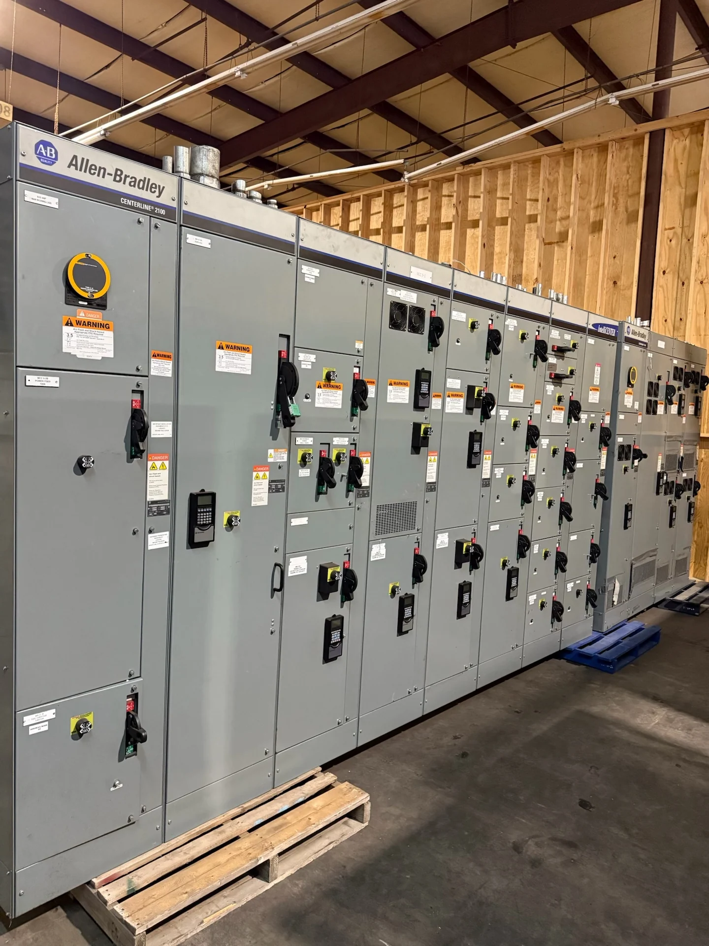
If variable frequency drives are included, define whether they will be mounted in the motor control center, supplied as coordinated adjacent equipment, or connected through a project-specific interface. Document drive horsepower, input and output connections, bypass philosophy, disconnecting means, line or load reactors where required by the design, and communication points. Heat dissipation deserves early attention because drive losses can influence enclosure ventilation and room conditions. Also reserve practical access for cable termination, keypad or network service, bucket removal, and testing. A custom manufacturer-built lineup can then coordinate power sections, control sections, and field interfaces before fabrication drawings are submitted.
Account for Water-Treatment Environment and Site Conditions
Water and wastewater facilities can expose electrical equipment to humidity, condensation, chemical vapors, washdown, dust, and temperature variation. The equipment specification should identify whether the lineup is indoors or outdoors, the installation area, ambient temperature range, elevation if relevant, ventilation provisions, corrosion concerns, enclosure requirements, and cleaning practices. Do not select an enclosure solely from a room label; match environmental protection to the actual exposure and the applicable project requirements. For a Tulsa installation, confirm building access, slab or housekeeping-pad dimensions, cable-entry direction, equipment movement path, working clearances, and anchorage details with the site team before the layout is finalized.
Define Controls, Interlocks, and Communications
Treatment plants often combine local controls, automatic sequences, level instruments, flow signals, permissives, alarms, and supervisory control. State which commands originate at a local operator station, programmable controller, remote system, or hardwired circuit, and identify the expected fail state for each motor. Specify HOA functions, remote-start permissives, emergency-stop interfaces, overload contacts, run and fault feedback, lead-lag rotation, and loss-of-communication behavior. Network details should name the intended protocol and data points without assuming compatibility. A clear I/O list and control narrative help the switchgear manufacturer separate power wiring from control wiring and identify terminal, fuse, relay, and interlock needs.
Prepare a Complete Manufacturer Quote Package
A useful request for motor control centers for water treatment pumps and process equipment should include the one-line diagram, motor schedule, site and environmental data, available fault information, enclosure requirements, lineup dimensions or room constraints, control schematics, network expectations, utility or owner standards, and requested documentation. Identify whether factory inspection, witness testing, shipping splits, lifting points, or special packaging will be required. Switchgear Builders manufactures new custom electrical equipment in the United States, using American components and offering nationwide shipping; project-specific configuration, component selection, documentation, and shipping terms still need to be confirmed.