Plan the Water-Treatment Distribution Context
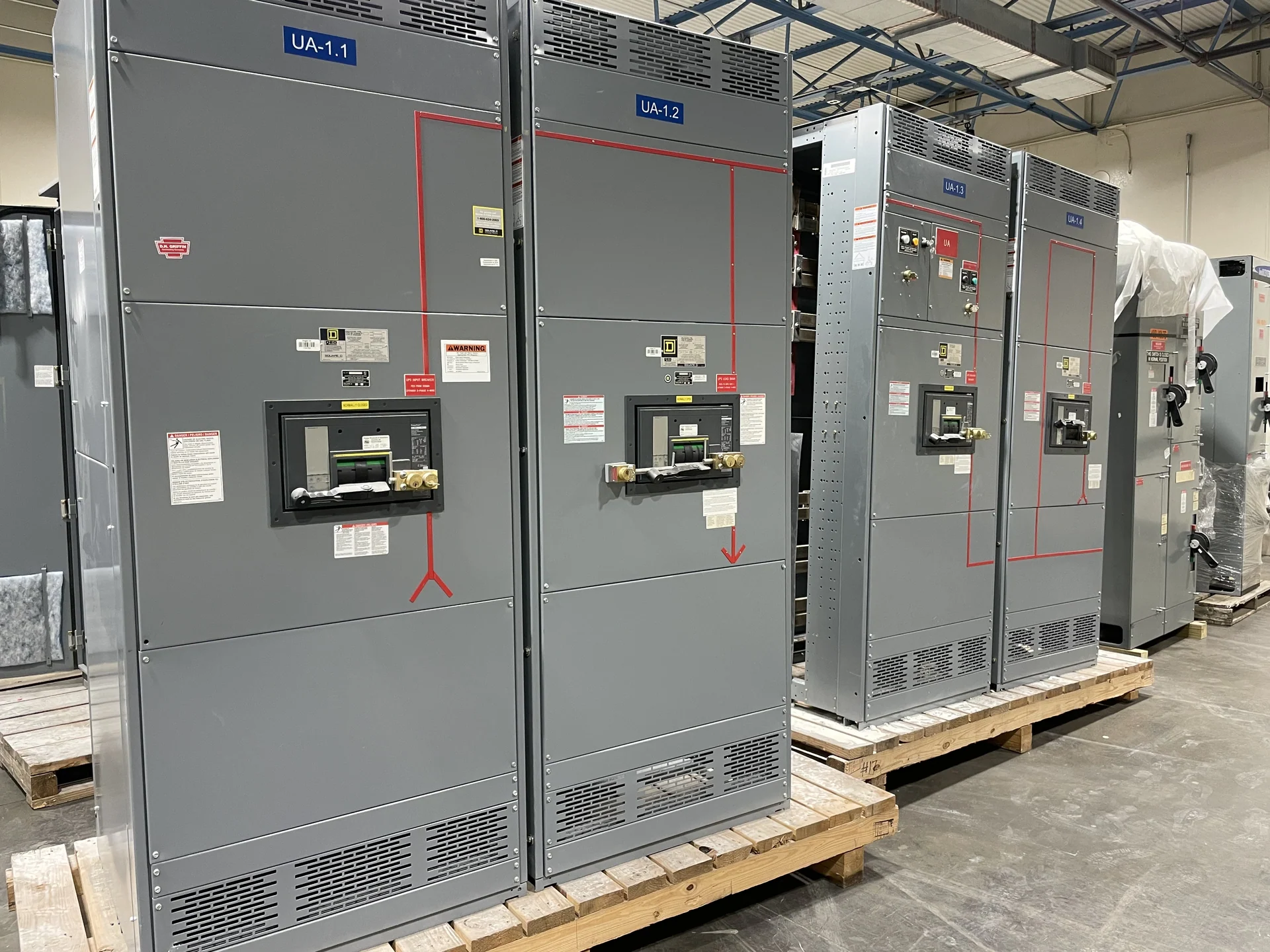
A Vermont water-treatment project should begin with a clear map of incoming power, process areas, motor loads, standby sources, and control-system interfaces. A motor control center may organize feeders, starters, variable frequency drives, disconnects, metering, and control terminals, but the right arrangement depends on the one-line diagram and operating sequence. Identify pump horsepower, voltage, phase, starting method, duty cycle, rotation requirements, fault-current information, and expansion needs before requesting a quote. Switchgear Builders manufactures new electrical distribution equipment in the United States, builds custom to specification, uses American components, and ships nationwide; project-specific service and delivery details should be confirmed during inquiry.
Evaluate Motor Starting and Feeder Coordination
Pump starting affects voltage behavior, upstream protection, mechanical equipment, and the continuity of treatment operations. Across-the-line starters can be straightforward for suitable motors, while reduced-voltage methods or drives may address starting-current, process-control, or acceleration requirements after engineering review. The equipment specification should identify motor full-load current, locked-rotor data when available, feeder length, transformer information, and the desired protective-device coordination. Review interrupting duty, continuous current, overload protection, grounding, and short-circuit requirements together rather than selecting a starter in isolation. Settings and final coordination remain project responsibilities for the qualified design team.
Choose Drives Around Process Behavior
Variable frequency drives can help a pump follow changing flow or pressure demands, but they introduce design questions beyond speed control. Confirm the motor’s compatibility, required speed range, bypass philosophy, harmonic considerations, heat dissipation, cable routing, grounding, and control-network method. Determine whether a drive is essential for a particular pump, preferred for energy or process control, or inappropriate for a duty that needs fixed-speed operation. A custom motor control center layout should reserve workable space for power and control wiring, provide maintainable access, and distinguish line-side, load-side, and low-voltage interfaces in the drawings.
Account for Vermont Environmental Conditions
Site conditions in Vermont can influence enclosure selection, heater or ventilation needs, corrosion considerations, cable entry, and the transition between an electrical room and outdoor process equipment. The design team should document indoor or outdoor placement, temperature range, moisture exposure, washdown practices, elevation, condensation risk, snow or ice exposure where applicable, and the building’s ventilation strategy. These inputs help define enclosure construction and environmental provisions without assuming a particular site rating. Confirm dimensions, working clearances, door swing, lifting path, housekeeping pads, and conduit routes before fabrication so the lineup can be received and installed safely.
Define Controls, Interlocks, and Signals
Water-treatment controls should be described as an operating sequence, not only as a list of devices. Explain local and remote start commands, permissives, emergency stops, fault indications, hand-off-auto behavior, lead-lag rotation, level or pressure inputs, alarm priorities, and the interface with a PLC or supervisory system. Identify required discrete and analog points, communication protocols, terminal schedules, shield and grounding practices, and any separation between power and control wiring. For each pump, document what happens after a drive fault, loss of control power, source transfer, or communications failure. The manufacturer can then align the custom assembly, drawings, and terminal arrangement with the approved sequence.
Prepare a Complete Manufacturer Inquiry
A useful Vermont switchgear inquiry should include the one-line diagram, load schedule, motor list, available fault current, system voltage and frequency, grounding method, enclosure location, dimensions, cable-entry direction, control narrative, required drawings, inspection expectations, and shipping destination. Include whether the equipment is part of a new plant, an expansion, or a replacement interface, along with site access and receiving constraints. Ask the manufacturer to identify assumptions, exclusions, component data, testing scope, and documentation included in the quote. Switchgear Builders can review a request for new custom equipment and coordinate nationwide shipping, while final applicability of any standard, listing, or project approval must be confirmed for the specific design.