Start with the Burlington Facility's Distribution Map
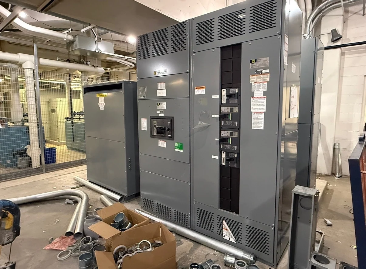
Planning medium-voltage switchgear for an industrial facility in Burlington, Vermont begins with a clear map of sources, transformers, feeders, and operating boundaries. Identify the utility service or generation source, nominal system voltage, frequency, phase arrangement, grounding method, transformer primary connections, and each downstream load group. A current one-line diagram should show normal and alternate paths, sectionalizing points, future feeders, and the location of protective devices. Site drawings also matter: room dimensions, cable entry, equipment movement, working clearances, elevation, heating, moisture exposure, and foundation interfaces can change the practical lineup arrangement. These inputs let an American manufacturer develop new equipment around the actual project rather than a generic catalog description.
Define Voltage Class and Fault Duty
Voltage class is not interchangeable with the nominal voltage printed on a utility bill or transformer schedule. The design team should confirm maximum system voltage, insulation coordination, basic impulse insulation level where applicable, frequency, grounding, and the prospective fault current at each switchgear location. Specify the required short-circuit withstand duty and the interrupting capability of the selected switching and protective devices, with calculations supplied by the responsible electrical engineer. Transformer impedance, utility contribution, motor contribution, generator operation, and parallel-source conditions can affect available fault current. For a Burlington industrial feeder project, these values should be documented before a manufacturer prepares a project-specific equipment scope or price.
Coordinate Transformer Connections and Feeders
Transformer connections determine more than cable termination details. Provide transformer kVA, primary and secondary voltage, winding connection, impedance, grounding arrangement, inrush considerations, neutral treatment, and the intended feeder direction. Then identify whether each medium-voltage feeder supplies a transformer, motor, process load, or another distribution section, including conductor size and termination preferences when known. The switchgear arrangement may need space for incoming connections, feeder switching, fuses or circuit breakers, metering, grounding provisions, and control wiring. A custom build should be checked against the physical route from the Burlington facility's service room to each transformer so cable bending, access, and maintenance activities remain workable.
Build a Protection and Relaying Basis
Protective relaying should be defined from the facility's coordination study, not selected by voltage class alone. Gather time-current curves, upstream utility settings, transformer damage curves, feeder load data, motor-starting information, ground-fault requirements, and any source-transfer or generator operating sequence. The engineer can then establish pickup values, time delays, instantaneous functions, phase and ground protection, breaker or switch trip logic, and communications points where applicable. Review coordination across the utility service, medium-voltage lineup, transformer primary protection, and low-voltage mains. The manufacturer can incorporate the agreed devices and control interfaces into new American-built switchgear, while final settings and field commissioning remain project responsibilities for qualified parties.
Confirm Construction, Documentation, and Review Gates
A useful inquiry should distinguish required construction from preferred features. State indoor or outdoor installation, enclosure and environmental requirements, bus material, lineup sections, access direction, cable entry, device arrangement, metering, control power, interlocks, nameplates, terminal points, and spare provisions. Include drawing standards, submittal expectations, inspection points, test records, and shipping splits. If the specification references UL 891, first confirm with the engineer whether that standard applies to the proposed assembly and what project-specific listing or verification is required; applicability is not automatic for every medium-voltage switchgear design. Design review should resolve these questions before fabrication, with changes documented through an agreed approval process.
Request New Switchgear for Nationwide Shipment
Switchgear Builders manufactures, builds, and supplies new electrical switchgear in the United States, custom to project specifications, with American components and nationwide shipping. A request for medium-voltage switchgear for industrial facilities in Burlington should include the one-line diagram, equipment schedule, fault-duty study, transformer data, relay requirements, room and cable-entry drawings, desired documentation, destination, and site delivery constraints. The manufacturer can use that package to clarify scope, identify open engineering decisions, and prepare project-specific equipment information. Ask for shipping sections, approximate weights, lifting points, packaging responsibilities, receiving access, and freight terms so the electrical contractor and qualified rigging team can coordinate delivery and placement.