Start With the Generator-to-Lineup Interface
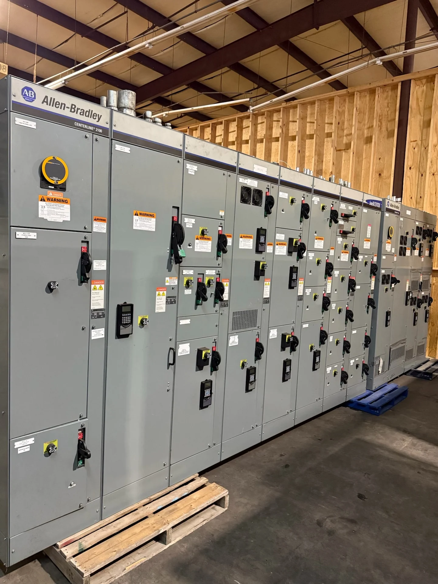
A generator and switchgear interface guide should begin with the electrical boundary between the generator package and the distribution lineup. Define the generator terminals, feeder conductors, generator breaker, neutral arrangement, grounding electrode connection, control wiring, and communications path before selecting an enclosure layout. The one-line diagram should show each source, bus section, tie, load group, and alternate operating condition. Confirm generator voltage, phase, frequency, continuous and short-circuit duties, source configuration, and the intended operating sequence with the engineer and generator supplier. Those inputs allow an American manufacturer to develop new custom switchgear with U.S. components and ship the completed equipment nationwide, subject to project scope and engineering review.
Generator Breaker Selection and Protection
The generator breaker is more than a disconnect: its interrupting capability, continuous current rating, trip functions, sensing arrangement, and control power must match the generator and the distribution system. Review generator subtransient behavior, available fault current, decrement characteristics, and the downstream coordination study rather than assuming a utility-source breaker scheme will transfer unchanged. Decide whether the breaker is fixed or drawout, identify shunt trip and closing requirements, and document undervoltage, overcurrent, ground-fault, reverse-power, or other functions only when the project requires them. Protection settings belong to the qualified engineer and should be recorded with the final lineup documentation, not inferred from a generic switchgear template.
Grounding, Neutral, and Bonding Decisions
Grounding decisions affect both the generator connection and the switchgear bus arrangement. Establish whether the generator neutral is solidly connected, switched, or separately derived under the project design, and coordinate that decision with the transfer equipment, system bonding point, grounding electrode conductor, and ground-fault sensing method. A switched neutral can change fault-current paths and sensing behavior; a solid neutral can create different parallel-current concerns. Show equipment grounding conductors, bonding jumpers, enclosure bonding, and any grounding resistor or transformer interface on the design documents. The manufacturer can build the specified new assembly, but the engineer of record must confirm the grounding method, applicable electrical rules, and installation details for the site.
Transfer and Source-Interlocking Logic
Transfer logic determines how the generator source interacts with the normal source, so document the sequence in plain language as well as on the schematic. Identify permissives for generator available, breaker open or closed, source voltage, emergency stop, and load shedding where applicable. Define whether the arrangement is open transition, closed transition, bypass-assisted, or another project-specific scheme, and state which devices are mechanically or electrically interlocked. Preventing unintended paralleling requires agreement among the generator controller, automatic transfer equipment, switchgear controls, protective relays, and operator controls. Include test positions, local-versus-remote control, alarm contacts, and fail-safe behavior in the review package before fabrication.
Synchronization and Paralleling Interfaces
Synchronization is a system function that requires more than matching nominal voltage and frequency. If the project permits a generator to parallel with another source, identify the synchronizer, permissive logic, sync-check relay, breaker close timing, metering signals, governor and voltage-regulator interfaces, and protective functions that supervise the connection. Specify whether paralleling is momentary or sustained and define the operating states that require load sharing, import-export control, or reverse-power protection. If the generator is intended only for isolated emergency operation, say so explicitly and omit unnecessary paralleling assumptions. The final control scheme should be reviewed with the generator controls provider and electrical engineer before a custom lineup is released for manufacture.
Testing, Documentation, and Shipping Coordination
A useful equipment package connects design decisions to inspection and commissioning activities. Agree on point-to-point wiring checks, breaker operation checks, interlock verification, control-power checks, insulation or continuity checks where applicable, relay setting records, and witnessed functional scenarios. The test plan should identify which conditions can be simulated at the manufacturer and which require field equipment or an energized system, with acceptance criteria documented for each check. Provide approved one-lines, schematics, terminal schedules, device data, lifting information, shipping splits, destination details, and receiving constraints. Switchgear Builders manufactures new equipment in the United States, custom to specification with American components, and coordinates nationwide shipping requirements based on the defined project package; transit timing and site handling remain project-specific.