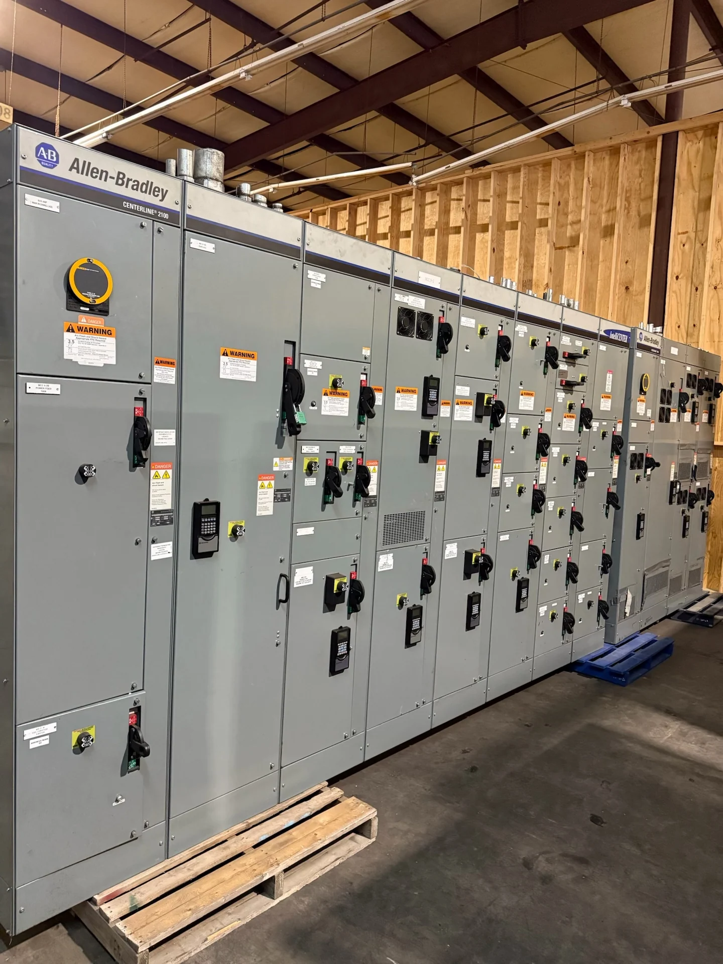
Start with the Transformer and System Data
A reliable transformer and switchgear interface begins with one consistent set of electrical inputs. Record the transformer primary and secondary voltages, phase and frequency, winding connection, grounding arrangement, kVA rating, impedance, and available fault-current information. Identify whether the distribution equipment connects directly to the transformer secondary, through a feeder, or through a busway section. The transformer nameplate, utility requirements, one-line diagram, and load study should agree before a new switchgear design is finalized. When information is incomplete, mark assumptions clearly rather than allowing a nominal voltage or estimated fault duty to drive the equipment specification. Also record transformer tap position, whether taps are adjustable under load, and the expected operating range so protection and voltage assumptions remain aligned.
Match Voltage, Current, and Insulation Requirements
Transformer secondary voltage establishes the nominal system that the connected switchgear must serve, but nominal voltage alone is not enough. The design team should verify phase arrangement, line-to-line and line-to-neutral relationships, continuous current, conductor configuration, and grounding method. Transformer full-load current helps frame the main device and bus requirements, while calculated load and future capacity determine whether the lineup needs additional feeder space or a different current rating. For medium-voltage interfaces, confirm equipment voltage class, insulation coordination, and applicable impulse requirements separately from the transformer nameplate voltage. For a delta or wye interface, identify which terminals are brought to the lineup and whether a neutral is required for loads, sensing, or grounding.
Account for Impedance and Fault Duty
Transformer impedance affects available secondary fault current and therefore influences protective-device interrupting ratings, bus bracing, conductor selection, and coordination studies. A lower impedance can produce higher fault current, while parallel transformers or multiple sources can change the result further. The engineer should calculate fault duty at the switchgear line terminals and at significant downstream buses rather than copying a generic value into a quote request. Include utility contribution, transformer data, generator or inverter sources, grounding details, and planned operating configurations so the manufacturer can review the intended equipment duty with the project engineer. Document transformer secondary conductor length and routing because those details can affect calculated impedance between the transformer terminals and the switchgear main device.
Define the Physical Connection
Electrical compatibility must be matched by a buildable physical interface. Confirm transformer secondary termination locations, phase orientation, cable quantity and size, bending space, bus duct dimensions, entry direction, neutral and grounding conductor paths, and the relative elevations of the two assemblies. Room access, working clearances, ventilation, fire separations, housekeeping pads, and seismic anchorage can affect enclosure dimensions and shipping splits. A dimensioned plan, elevation, connection detail, and cable schedule reduce field surprises. If the transformer and switchgear come from different design packages, assign responsibility for each interface dimension and connection detail before fabrication. Check that phase labels, rotation, and termination hardware use the same convention on both drawings; a corrected field connection should not be left to installer interpretation.
Coordinate Protection and Operating Sequences
The transformer main protective device should be evaluated with primary protection, secondary protection, feeder devices, and any transfer or tie arrangement as one system. Review time-current characteristics, transformer inrush, ground-fault protection, selective coordination objectives, and the operating states described by the one-line diagram. A main-tie-main lineup, generator source, or maintenance bypass can introduce alternate current paths that change fault calculations and interlocking needs. Provide proposed settings, relay functions, control voltage, metering points, and source status requirements for engineering review; final settings remain a project responsibility rather than a default feature of the enclosure.
Prepare a Complete Manufacturer Quote Package
A useful request for a custom switchgear quote should include the one-line diagram, transformer schedules, fault study inputs, load schedule, specifications, physical drawings, environmental conditions, utility requirements, and delivery destination. State whether the equipment is indoor or outdoor, identify enclosure and access constraints, and list required breakers, switches, metering, controls, communications, and documentation. Switchgear Builders manufactures and supplies new electrical switchgear in the United States, custom to specification with American components and nationwide shipping. Project-specific ratings, construction details, standards, and any UL 891 applicability or listing requirement must be reviewed and confirmed for the particular assembly before an order is defined.