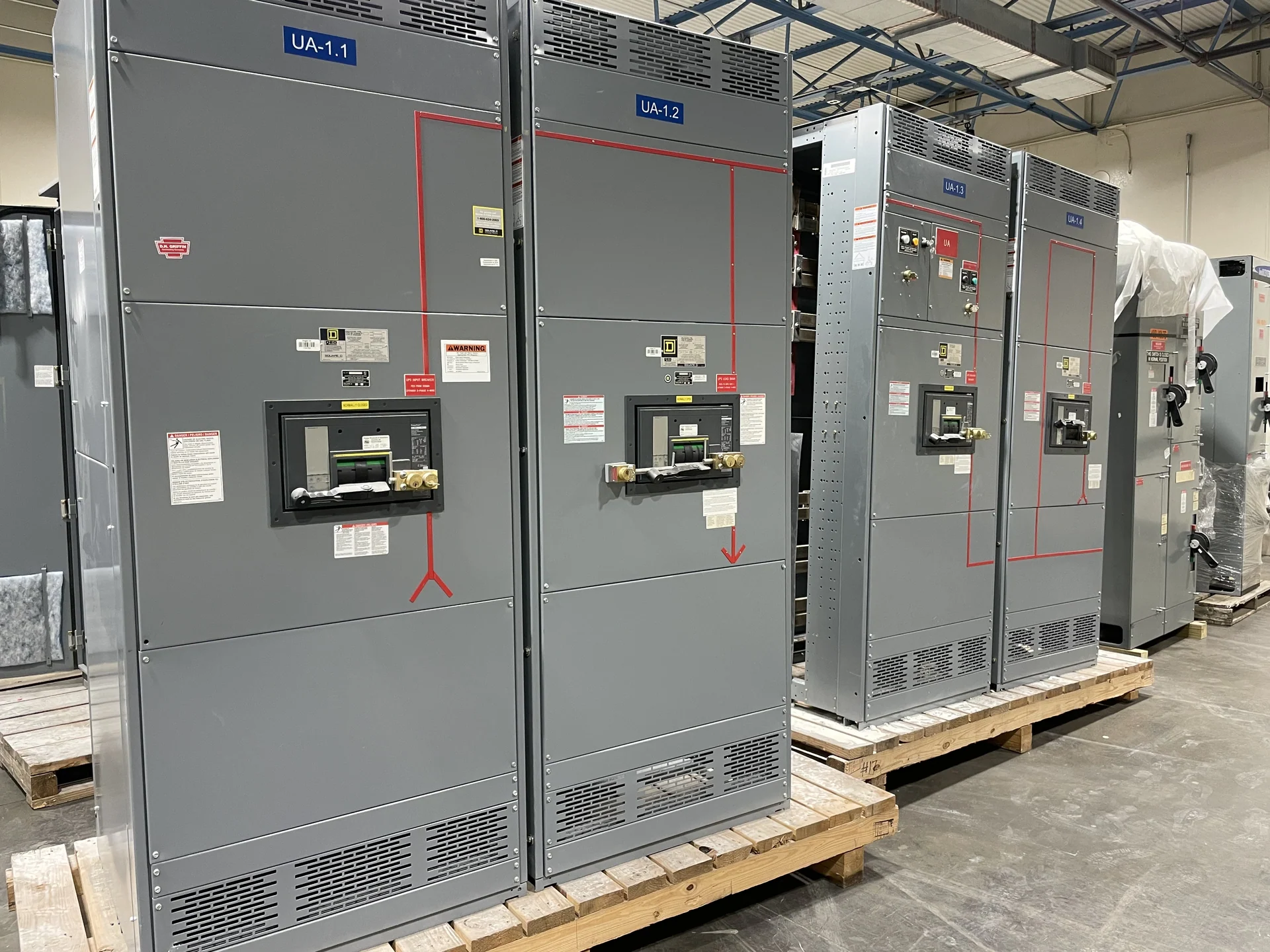
Start With the One-Line and Equipment Arrangement
Planning cable entry for switchgear begins with the electrical one-line diagram and the physical lineup arrangement, not with a conduit location chosen in isolation. Identify incoming sources, outgoing feeders, transformer connections, neutral conductors, grounding conductors, and any bus connections that terminate at the assembly. Then establish which sections contain mains, ties, or feeder devices and where cable compartments or termination areas can be placed. A custom manufacturer-built lineup can be coordinated around these interfaces, but the final arrangement should be reviewed by the responsible engineer, installer, and equipment manufacturer before fabrication.
Choose Top or Bottom Entry Deliberately
Top entry may align with overhead conduit, cable tray, or a ceiling route, while bottom entry may simplify connections from a trench, raised floor, or underground raceway. The choice affects enclosure depth, termination orientation, lifting and handling, field access, and the available path for conductors between the entry point and device terminals. It can also influence where sections must be split for shipping. Compare both options against the actual room geometry and installation sequence rather than assuming one is universally preferable. Switchgear Builders can build new equipment to project requirements, with the selected entry arrangement defined in the approved drawings.
Reserve Bend Space and Working Room
Cable entry planning must preserve practical bend space for the conductor size, insulation construction, and termination method specified by the project. A straight-line measurement from the conduit opening to the terminal is not enough; cables need room to turn without excessive force, crowding, or interference with barriers, shutters, doors, and adjacent phases. Account for the approach direction, minimum bend information supplied by the cable manufacturer, lug orientation, and the space needed for installation tools. The electrical contractor should verify field routing and access, while the equipment design should show entry openings and termination zones clearly enough for coordinated installation.
Coordinate Conduit, Tray, and Structural Interfaces
Conduit locations, cable tray elevations, sleeves, housekeeping pads, and wall penetrations should be coordinated with the switchgear footprint before concrete, framing, or raceway work is finalized. Show entry points in relation to section joints, doors, removable plates, lifting provisions, and anchorage so that a raceway does not block service access or land across an unsuitable compartment. Confirm whether conductors enter each section independently or pass through a shared wireway, and identify any separation required between power, control, and communication wiring. These details belong in the submittal review, where dimensions and interfaces can be checked against the project drawings.
Define Terminals, Grounding, and Field Access
A useful cable-entry specification identifies conductor material, number and size of cables per phase, neutral requirements, grounding method, termination hardware, and the intended lug or connector arrangement. It should also state which terminals must remain accessible after installation and whether removable covers or plates are needed for pulling and landing conductors. Consider how an installer will reach the connection points, torque hardware, inspect terminations, and close the compartment without disturbing adjacent wiring. Grounding and bonding paths require their own review, especially where entry plates, conduit fittings, or sectionalized enclosures are involved. Final details depend on the engineer's design and applicable project requirements.
Capture Entry Details in the Quote and Drawings
When requesting a quote for new custom switchgear, provide the one-line diagram, equipment schedule, available room dimensions, entry direction, conduit or tray drawings, conductor schedule, terminal requirements, and any installation constraints. Ask that the proposal and submittal drawings identify entry locations, usable termination space, section boundaries, removable covers, and shipping splits. Include the destination for nationwide shipping and explain site access or unloading limitations without assuming a delivery method. American components and a manufacturer-built assembly can be coordinated to the documented scope, but project-specific ratings, dimensions, interfaces, and acceptance requirements should be confirmed before approval.